01 / Mechanical Engineer

Mechanical Design

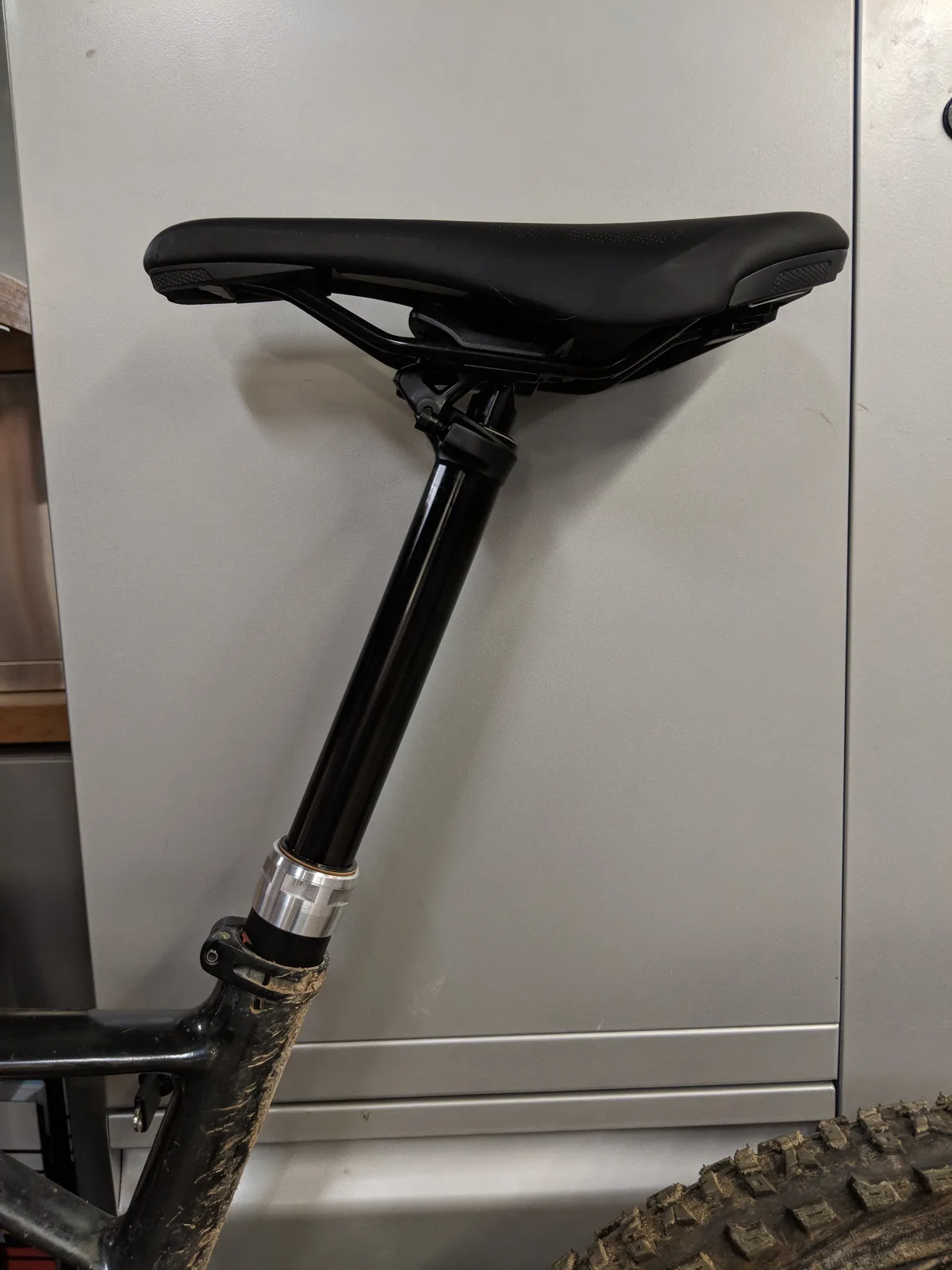
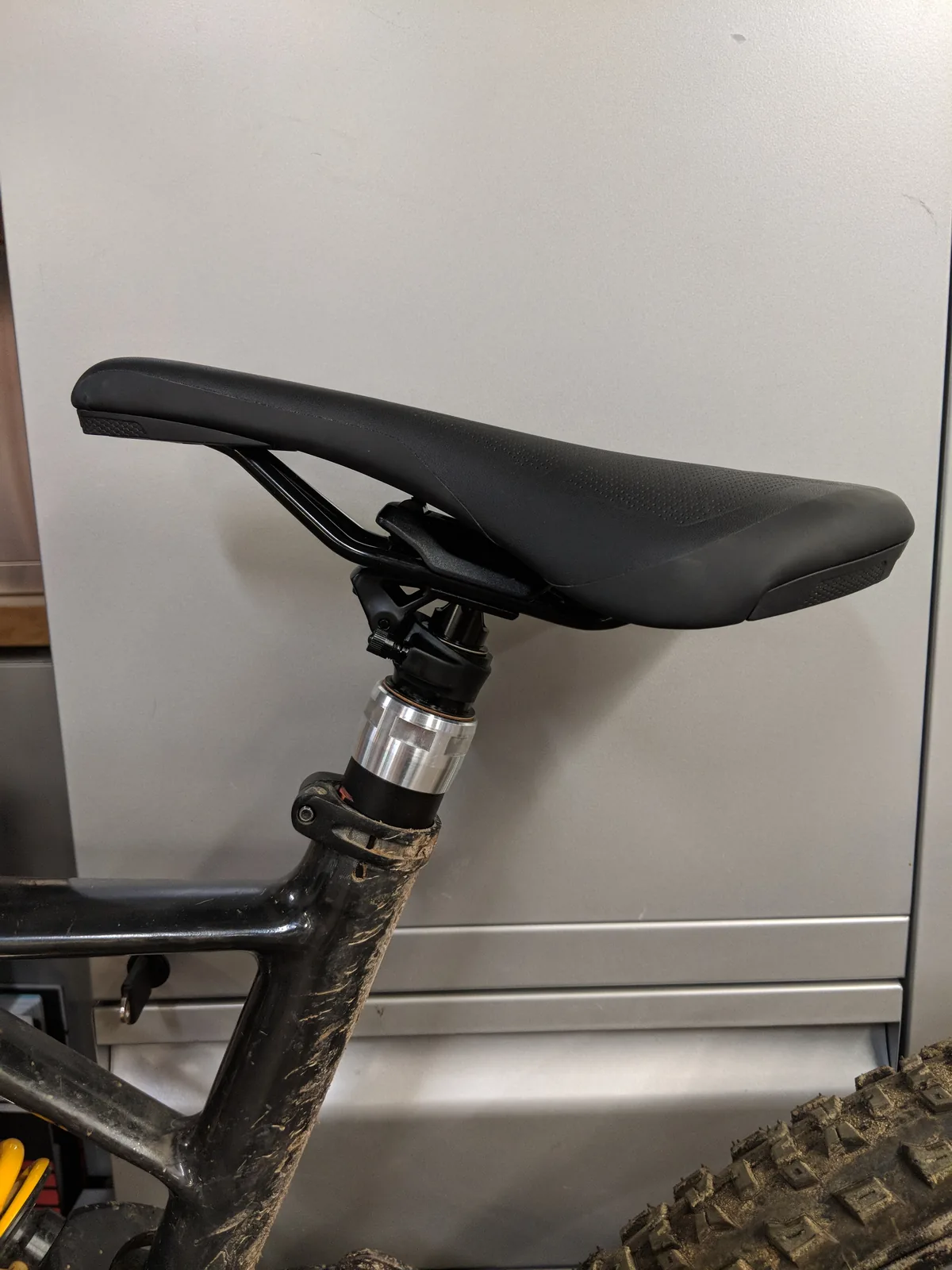
I engineered two production dropper-post products, from first sketch to 100k units a year. The work is predominantly machine design: load cases, tolerance stacks, and hundreds of detailed parts that all have to fit, seal, and survive.

ADVANCED MACHINE DESIGNCADFEAPRODUCTION PRODUCTS

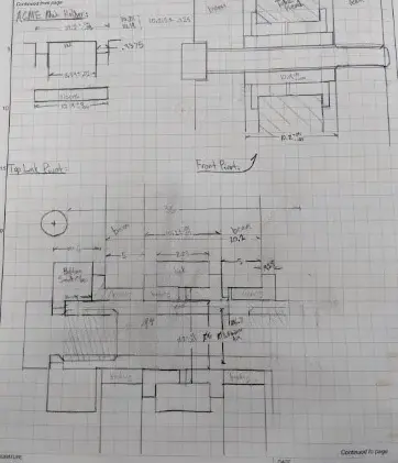
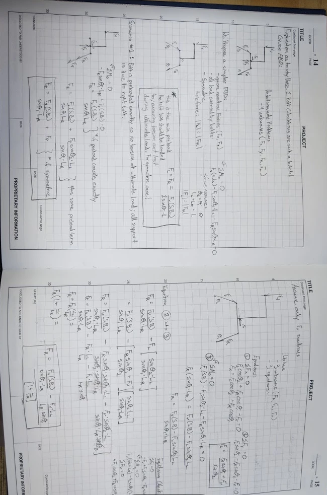
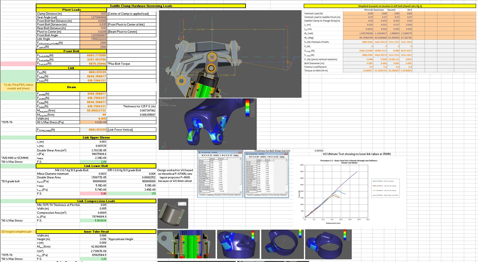
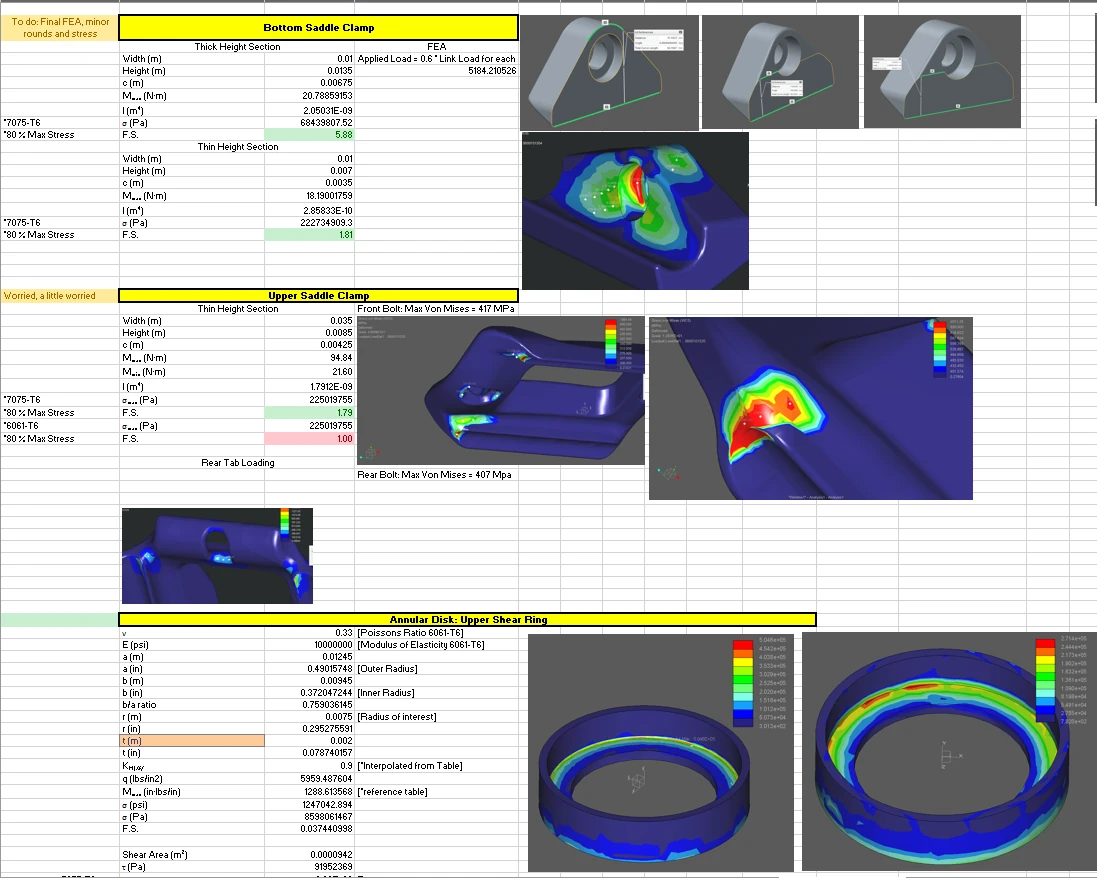
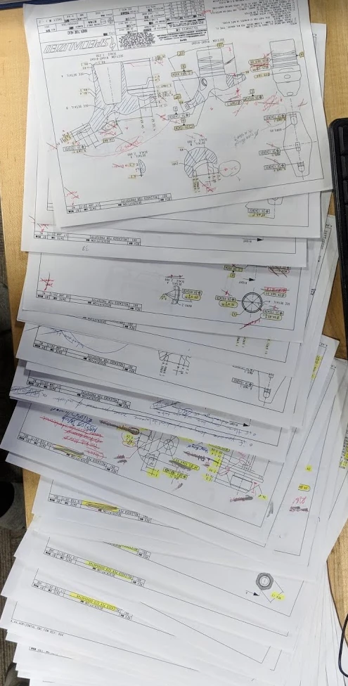
The 34.9 Command Post was designed from concept to mass production. It started with a free-body diagram and a clear picture of the static and dynamic loads the post would see, then moved into part-by-part iteration aimed at minimizing mass while holding strength and stiffness targets. The program produced 96 designed parts and 109 pages of 2D documentation, and reached proof of concept in eight months.

Command Post 34.9
Early concept sketch — defining the architecture before any CAD.
FIG 01Early concept sketch — defining the architecture before any CAD.
Free-body diagram and hand calculations: static and dynamic load cases.
FIG 02Free-body diagram and hand calculations: static and dynamic load cases.
Full CAD assembly.
FIG 03Full CAD assembly.
Exploded view — component breakdown.
FIG 04Exploded view — component breakdown.
Assembly section, collapsed.
FIG 05Assembly section, collapsed.
Hand calcs and supporting FEA.
FIG 06Hand calcs and supporting FEA.
Structural analysis across the load cases.
FIG 07Structural analysis across the load cases.
Part of the 109-page 2D drawing package.
FIG 08Part of the 109-page 2D drawing package.
Prototype hardware and components on the bench.
FIG 09Prototype hardware and components on the bench.
Production release — the program reached mass production.
FIG 10Production release — the program reached mass production.
Dropper Post — WU LT

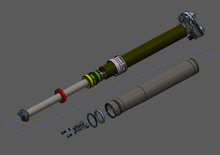
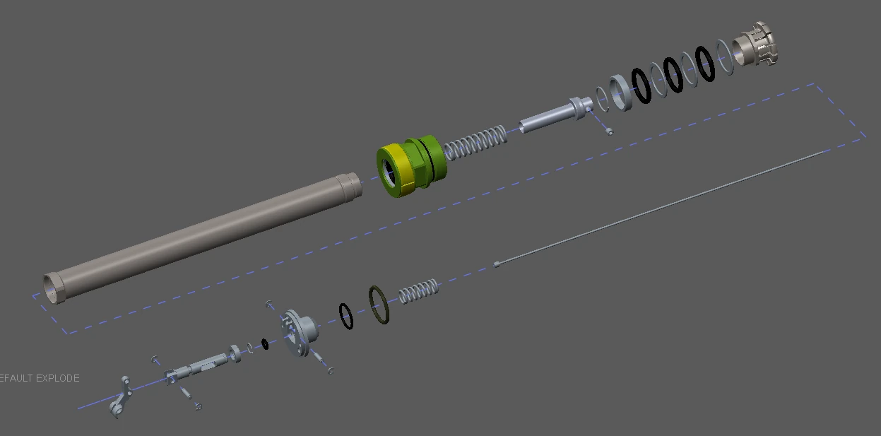
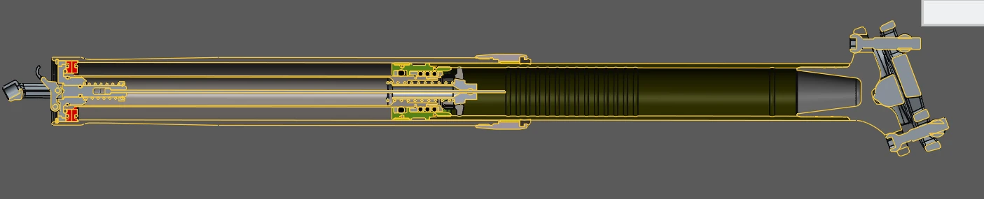
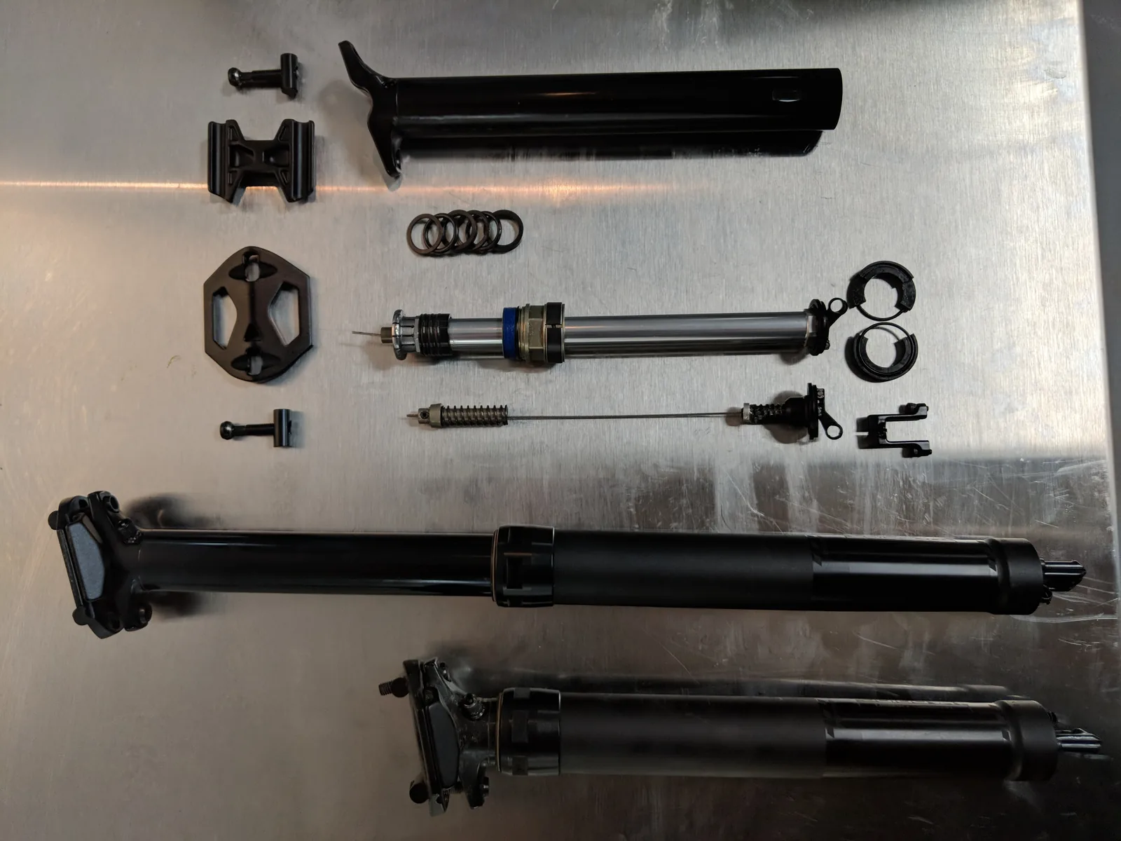
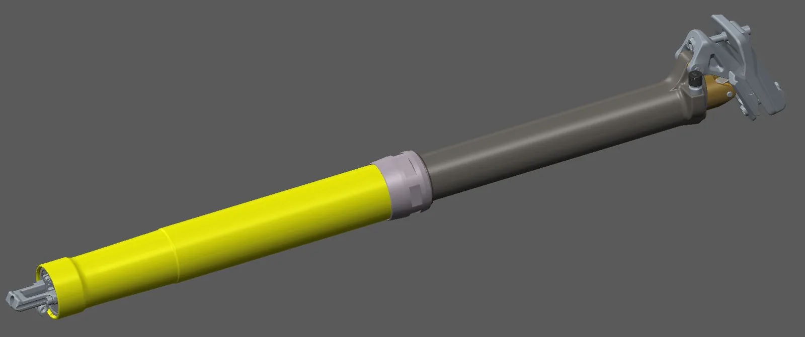
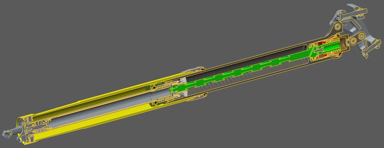
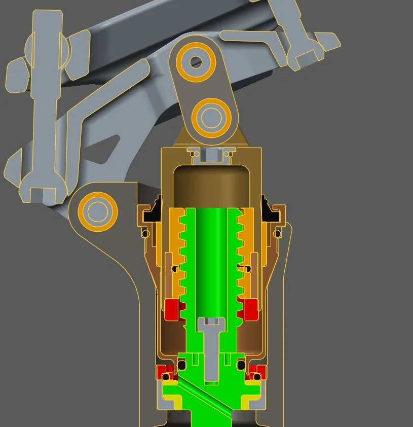
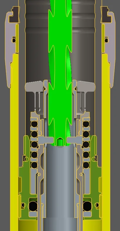
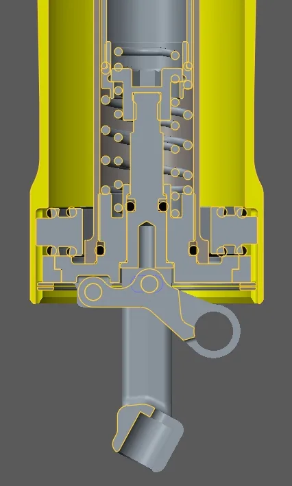
The WU LT dropper post introduced another degree of articulation as the post changed travel. The cross-sections below show the sealing, bushing, and most of the parts. This one was a fun challenge.

Full assembly (CAD).
FIG 11Full assembly (CAD).
Full-assembly cross-section.
FIG 12Full-assembly cross-section.
Upper internal section.
FIG 13Upper internal section.
Mid internal section.
FIG 14Mid internal section.
Lower internal section.
FIG 15Lower internal section.
Installed on the test bike.
FIG 16Installed on the test bike.
Dropped, under rider weight.
FIG 17Dropped, under rider weight.