02 / Mechanical Engineer

Composite Manufacturing & Design

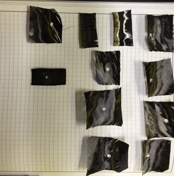
I designed and built structural carbon parts end to end: tooling, layup, cure time and temp. We treated composites as something you can analyze and optimize from first principles, not just lay up and hope — but sometimes that accuracy eludes you.

LAYUP SCHEDULE DESIGNCOMPOSITE TOOLING DESIGNMANDREL DESIGNUS-MANUFACTURABLE PROCESSES

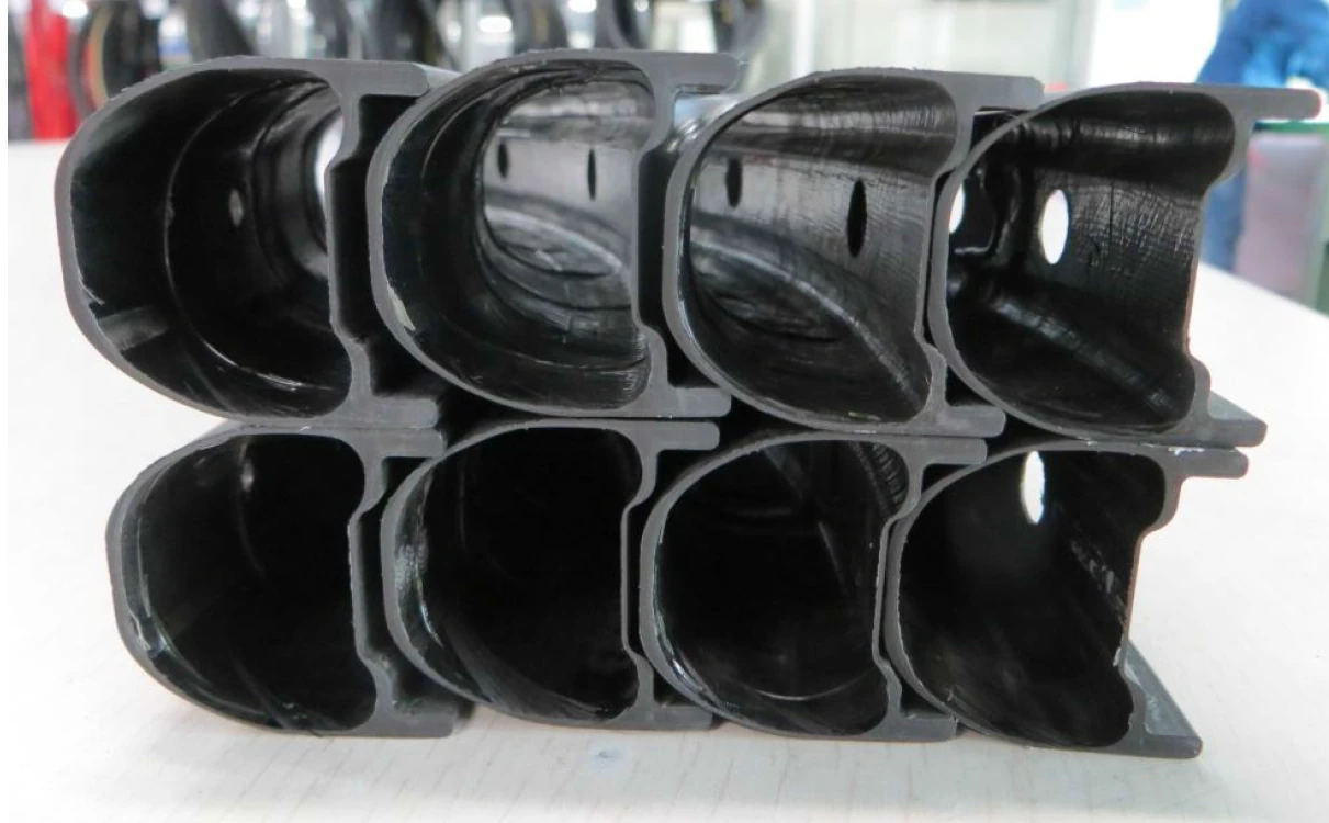
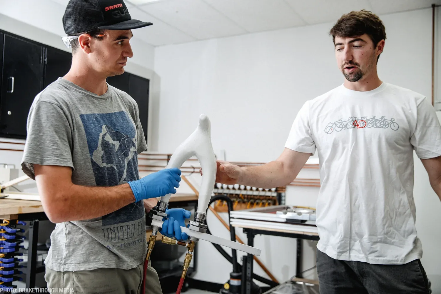
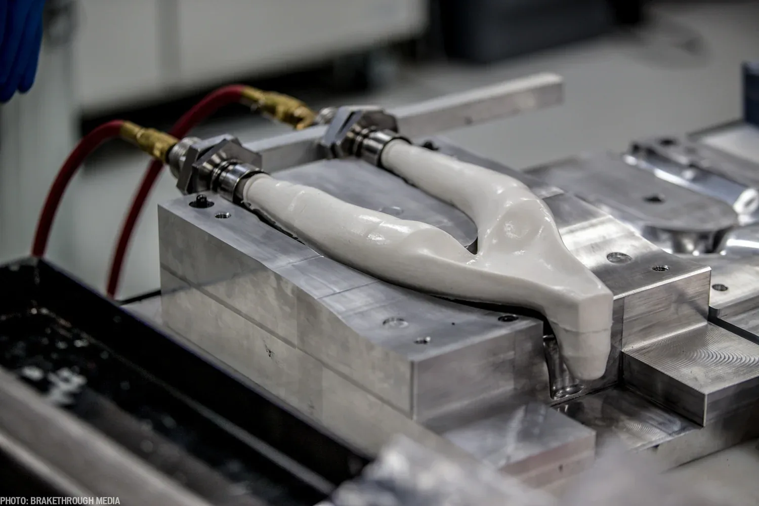
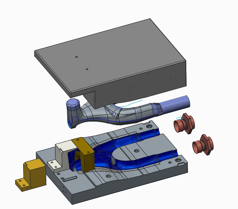
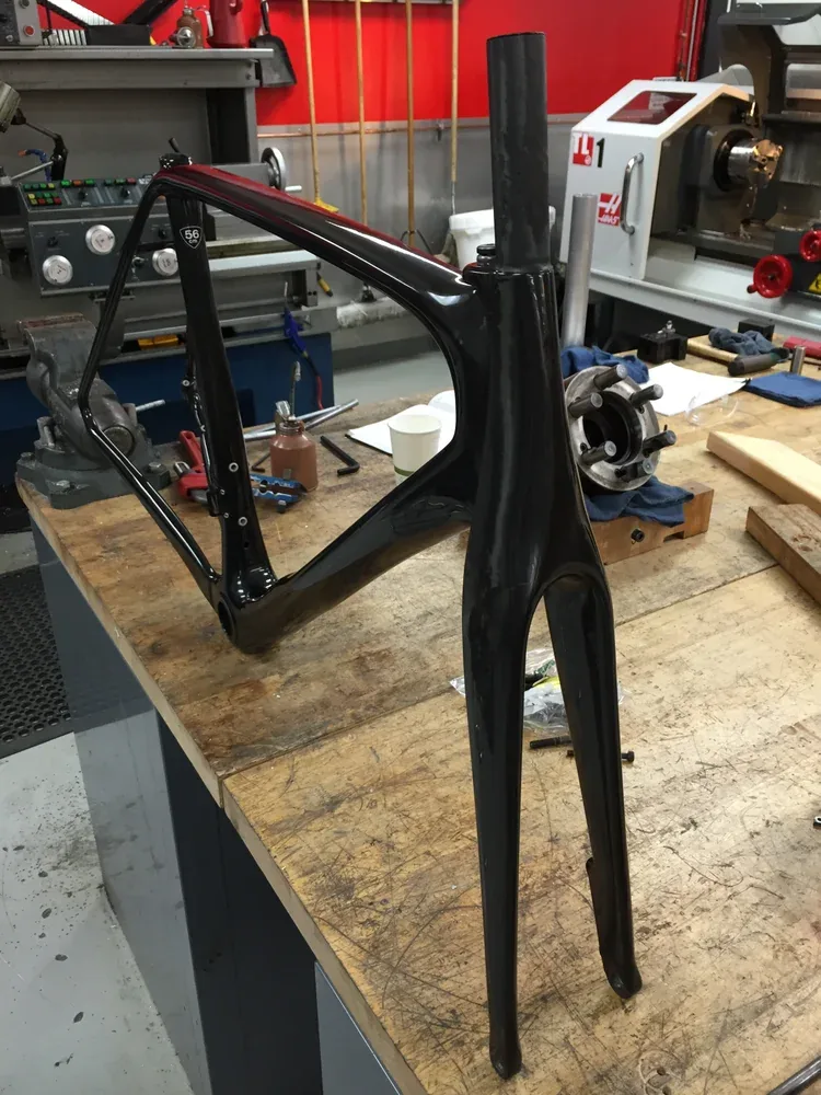
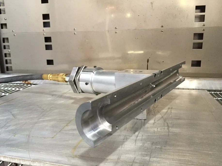
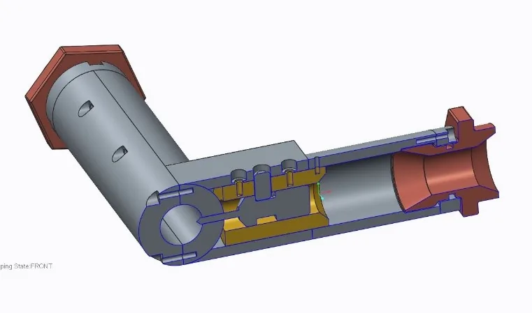
Starting from napkin sketches and moving to 3D CAD, the goal each time was a structurally sound, functioning prototype. To get there quickly, we developed an in-house process for fabricating silicone mandrels to prototype hollow composite structures — the tooling that lets a one-off carbon part exist at all. I designed the wheelset and seatpost for the EPIC model family, taking a first-principles approach to validate different cross-sections that maximized impact resistance while minimizing mass.

Layup & Tooling
Layup in progress on the shop floor.  Photo: BrakeThrough Media.
FIG 01Layup in progress on the shop floor. Photo: BrakeThrough Media.
The versatile mandrel, bladder and rubber chicken.  Photo: BrakeThrough Media.
FIG 02The versatile mandrel, bladder and rubber chicken. Photo: BrakeThrough Media.
Mandrel and tooling we designed.
FIG 03Mandrel and tooling we designed.
Mandrel and tooling design (CAD).
FIG 04Mandrel and tooling design (CAD).
Prototype frame and fork.
FIG 05Prototype frame and fork.
X7 prototype on the bike.
FIG 06X7 prototype on the bike.
Shear-Out Resistance

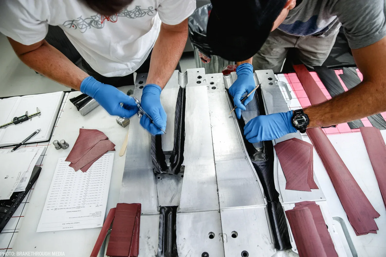
One process innovation: improving the shear-out resistance of composite joints by piercing holes during the minimum-viscosity point of the cure cycle — when the resin is fluid enough to flow around the fibers rather than cutting through them, leaving a far stronger hole.

Holes pierced at the minimum-viscosity point of the cure.
FIG 07Holes pierced at the minimum-viscosity point of the cure.
Detail of the pierced hole.
FIG 08Detail of the pierced hole.
Pull-out / shear test fixture.
FIG 09Pull-out / shear test fixture.
Control SL Wheel Set Design

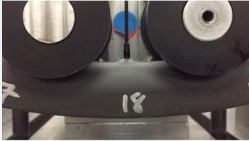
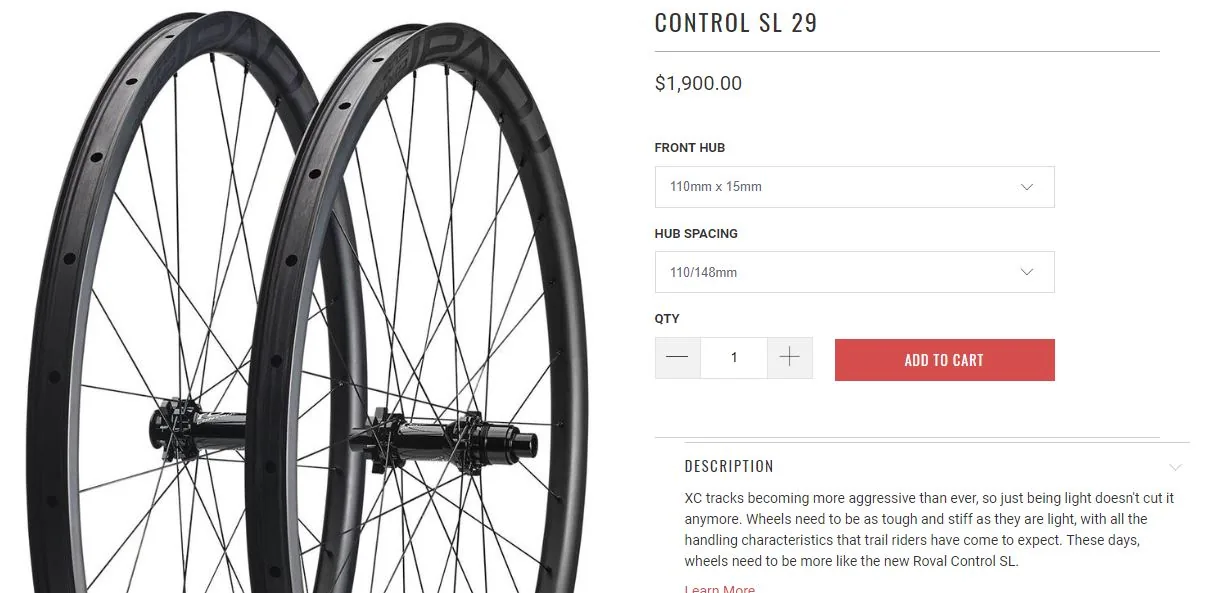
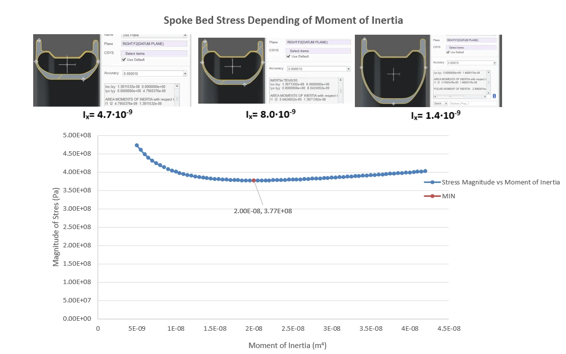
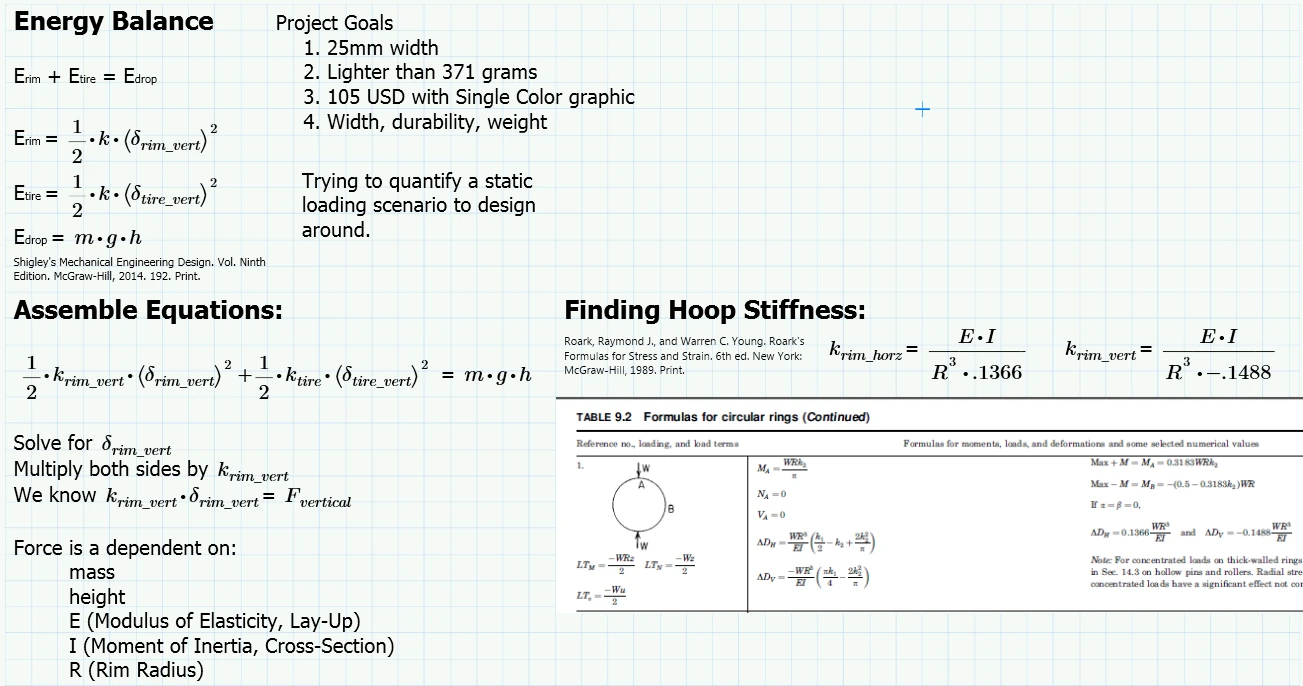
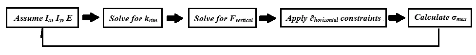
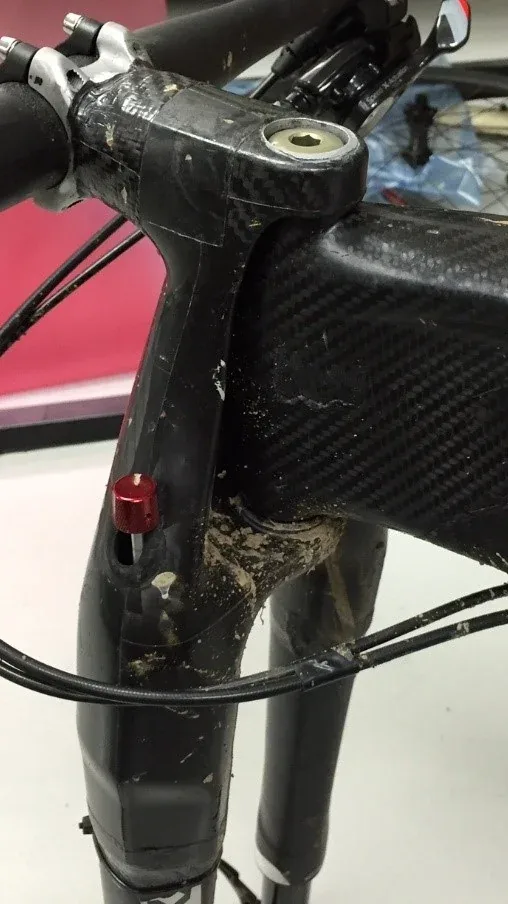
During impact testing, the spoke bed on the previous-generation Control SL failed under a compressive stress. Rather than simply adding material, I ran a design study: varying the cross-section height across a realistic range revealed a minimum stress at an ideal geometry, driving higher impact-energy tolerance without a mass penalty.

The wheelset, in production.
FIG 10The wheelset, in production.
Production rims I designed, cross-sectioned for inspection.
FIG 11Production rims I designed, cross-sectioned for inspection.
First-ply failure inspection.
FIG 12First-ply failure inspection.
Spoke-bed stress vs. cross-section moment of inertia — the minimum sets the target geometry.
FIG 13Spoke-bed stress vs. cross-section moment of inertia — the minimum sets the target geometry.
Model for rim cross-section optimization.
FIG 14Model for rim cross-section optimization.
Model workflow.
FIG 15Model workflow.